DIYry: Difference between revisions
Jump to navigation
Jump to search
No edit summary |
No edit summary |
||
| (13 intermediate revisions by the same user not shown) | |||
| Line 6: | Line 6: | ||
!Source | !Source | ||
!Components | !Components | ||
!Circuit | |||
!Schematic | !Schematic | ||
! | !Notes | ||
!Entry | !Entry | ||
|- | |- | ||
| Line 14: | Line 15: | ||
|[https://shop.evilmadscientist.com/productsmenu/652 The Three Fives Kit: A Discrete 555 Timer] | |[https://shop.evilmadscientist.com/productsmenu/652 The Three Fives Kit: A Discrete 555 Timer] | ||
|Evil Mad Scientist | |Evil Mad Scientist | ||
| | |||
| | | | ||
| | | | ||
| Line 23: | Line 25: | ||
|[https://underbelly.nu/product/drawdio-building-kit/ Drawdio Pencil Synth] | |[https://underbelly.nu/product/drawdio-building-kit/ Drawdio Pencil Synth] | ||
|Reverse Landfill | |Reverse Landfill | ||
| | |||
| | | | ||
| | | | ||
| Line 32: | Line 35: | ||
|[https://www.makerspaces.com/vsc/ Learn To Make A Very Simple Circuit] | |[https://www.makerspaces.com/vsc/ Learn To Make A Very Simple Circuit] | ||
|Makerspaces | |Makerspaces | ||
| | |||
| | | | ||
| | | | ||
| Line 41: | Line 45: | ||
|[https://www.instructables.com/Build-a-Simple-Circuit-from-a-Pizza-Box-No-Solder/ Build a Simple Circuit From a Pizza Box (No Soldering)] | |[https://www.instructables.com/Build-a-Simple-Circuit-from-a-Pizza-Box-No-Solder/ Build a Simple Circuit From a Pizza Box (No Soldering)] | ||
|Instructables | |Instructables | ||
| | |||
| | | | ||
| | | | ||
| Line 65: | Line 70: | ||
|1 | |1 | ||
|} | |} | ||
| | |||
| | | | ||
| | | | ||
| Line 75: | Line 81: | ||
| | | | ||
| | | | ||
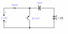
|[[File:Reverse bias oscillator circuit.jpg|thumb|source: http://www.next.gr/circuits/Reverse-Bias-Oscillators-l38609.html]] | |||
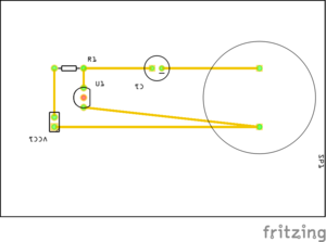
|[[File:Reverse-bias-oscillator pcb.png|thumb|PCB view of circuit diagram]] | |||
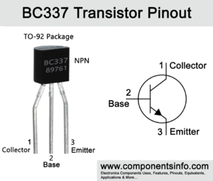
|[[File:Bc337-transistor-pinout-equivalent.gif|thumb]] | |||
| | | | ||
{| class="wikitable" | {| class="wikitable" | ||
|+ | |||
!No. | |||
!Prototype | |||
!Audio | |||
!Description | |||
!Status | |||
|- | |||
|1 | |||
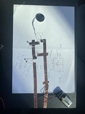
|[[File:Reverse-1.jpg|thumb]] | |||
|[audio test] [not actual audio] <audio src="https://hub.xpub.nl/soupboat/supwiki/images/6/6a/Halloumi.mp3"></audio> | |||
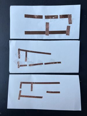
|First test of the circuit on paper + conductive tape | |||
|Working | |||
|- | |||
|2 | |||
|[[File:Paper circuit test.jpg|thumb]] | |||
| | |||
| | |||
| rowspan="2" |Not working | |||
|- | |- | ||
| | | | ||
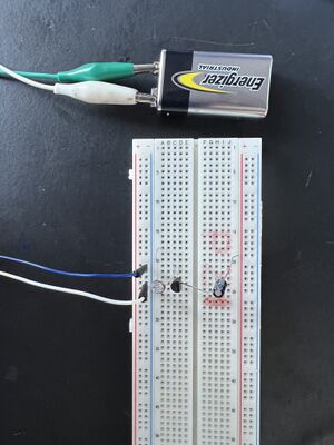
|[[File:Reverse-bias-oscillator-breadboard-2.jpg|thumb]] | |||
| | | | ||
| - There was a smell | |||
- Battery started overheating | |||
|} | |||
|} | |} | ||
{| class="wikitable" | {| class="wikitable" | ||
Latest revision as of 09:24, 14 June 2023
| No. | Type | Circuit | Source | Components | Circuit | Schematic | Notes | Entry | |||||||||||||||||||
|---|---|---|---|---|---|---|---|---|---|---|---|---|---|---|---|---|---|---|---|---|---|---|---|---|---|---|---|
| 1 | Kit | The Three Fives Kit: A Discrete 555 Timer | Evil Mad Scientist | ||||||||||||||||||||||||
| 2 | Kit | Drawdio Pencil Synth | Reverse Landfill | ||||||||||||||||||||||||
| 3 | DIY | Learn To Make A Very Simple Circuit | Makerspaces | ||||||||||||||||||||||||
| 4 | DIY | Build a Simple Circuit From a Pizza Box (No Soldering) | Instructables | ||||||||||||||||||||||||
| 5 | DIY | Paper Circuit Pin | SparkFun Electronics |
|
|||||||||||||||||||||||
| 6 | Reverse Bias Oscillator |
|
| Component | |||
|---|---|---|---|
| Hand Crank Generator |
