ASHBY DESCRIBES THE HOMEOSTAT: Difference between revisions
No edit summary |
No edit summary |
||
| Line 1: | Line 1: | ||
<p class="pt-link">[[ | <p class="pt-link">[[Steps Towards a (Media) Ecology#ASHBY_DESCRIBES_THE_HOMEOSTAT|Steps Towards a (Media) Ecology]]</p> | ||
<br> | <br> | ||
<p class="parallel-text"> | <p class="parallel-text"> | ||
Revision as of 10:41, 1 December 2020
Steps Towards a (Media) Ecology
Here Ashby describes the homeostat, a machine which models an organism in an ultra stable state (a state of homeostasis). I also reproduce the images on those pages (although I have changed the captions to fit this wiki’s format).


EXTRACT:
|...| Ashby, R. Design for a Brain (1952) pp. 100-103
Ashby writes:
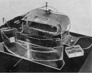
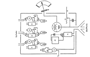
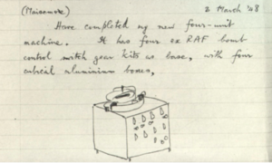
“The Homeostat [Fig: Homeostat, four units] consists of four units, each of which carries on top a pivoted magnet [Fig: Homeostat–magnet, coil, pivot, vane, and water]. The angular deviations of the four magnets from the central positions provide the four main variables. Its construction will be described in stages. Each unit emits a D.C. output proportional to the deviation of its magnet from the central position. The output is controlled in the following way. In front of each magnet is a trough of water electrode sat each end provide a potential gradient. The magnet carries a wire which dips into the water, picks up a potential depending on the position of the magnet, and sends it to the grid of the triode. J provides the anode-potential at 150 V., while H is at180 V. j so E carries a constant current. If the grid-potential allows just this current to pass through the valve, then no current will flow through the output. But if the valve passes more, or less, current than this, the output circuit will carry the difference in one direction or the other. So after E is adjusted, the output is approximately proportional to M's deviation from its central position.” [1]
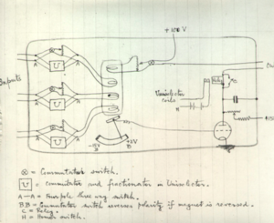
“Next, the units are joined together so that each sends its output to the other three; and thereby each receives an input from each of the other three. These inputs act on the unit's magnet through the coils A, B, and C, so that the torque on the magnet is approximately proportional to the algebraic sum of the currents in A, B, and C. (D also affects M as a self-feedback.) But before each input current reaches its coil, it passes through a commutator (X),which determines the polarity of entry to the coil, and through a potentiometer (P), which determines what fraction of the input shall reach the coil. As soon as the system is switched on, the magnets are moved by the currents from the other units, but these movements change the currents, which modify the movements, and so on. It may be shown […] that if there is sufficient viscosity in the troughs, the four-variable system of the magnet-positions is approximately state-determined. To this system the commutators and potentiometers act as parameters. When these parameters are given a definite set of values, the magnets show some definite pattern of behaviour; for the parameters determine the field, and thus the lines of behaviour. If the field is stable, the four magnets move to the central position, where they actively resist any attempt to displace them. If displaced, a co-ordinated activity brings them back to the centre. Other parameter-settings may, however, give instability; in which ease a 'runaway' occurs and the magnets diverge from the central positions with increasing velocity-till they hit the ends of the troughs. So far, the system of four variables has been shown to be dynamic, to have Figure 4/15/1 (A) as its diagram of immediate effects, and to be state-determined. Its field depends on the thirty-two parameters X and P. It is not yet ultrastable. But the inputs, instead of being controlled by parameters set by hand, can be sent by the switches S through similar components arranged on a uniselector (or 'stepping-switch') U. The values of the components in U were deliberately randomised by taking the actual numerical values from Fisher and Yates' Table of Random Numbers. Once built on to the uniselectors, the values of these parameters are determined at any moment by the positions of the uniselectors. Twenty-five positions on each of four uniselectors (one to each unit) provide 390,625 combinations of parameter-values. F represents the essential variable of the unit. Its contacts close when and only when the output current exceeds a certain value. When this happens, the coils G of the uniselector can be energised, moving the parameters to new values.”[…] [2]
- ↑ W. Ross Ashby, Design for a Brain, John Wiley and Sons Publishing, 1952 p 100
- ↑ W. Ross Ashby, Design for a Brain, John Wiley and Sons Publishing, 1952 pp 100-103 |Ashby’s notes on page 100-101 | It was given the name of' Homeostat ' for convenience of reference, and the noun seems to be acceptable. The derivatives homeostatic' and homeostatically', however, are unfortunate, for they suggest reference to the machine, whereas priority demands that they be used only as derivatives of Cannon's ‘homeostasis’. Following the original machine in principle, Mr. Earl .1. KIetsky, at the Technische Hogeschool, Delft, Holland, has designed and built a form that replaces the magnet, coils, vane and water by Kirchhoff adding circuits and capacitors